
MCU manufacturers usually provide protection of the non-volatile memory from read-out by debugging probes. At first glance, the main problem of cloning the firmware of the device is solved.
However, having obtained unencrypted firmware one can analyze the workflow of the code, and even change it as they wish.
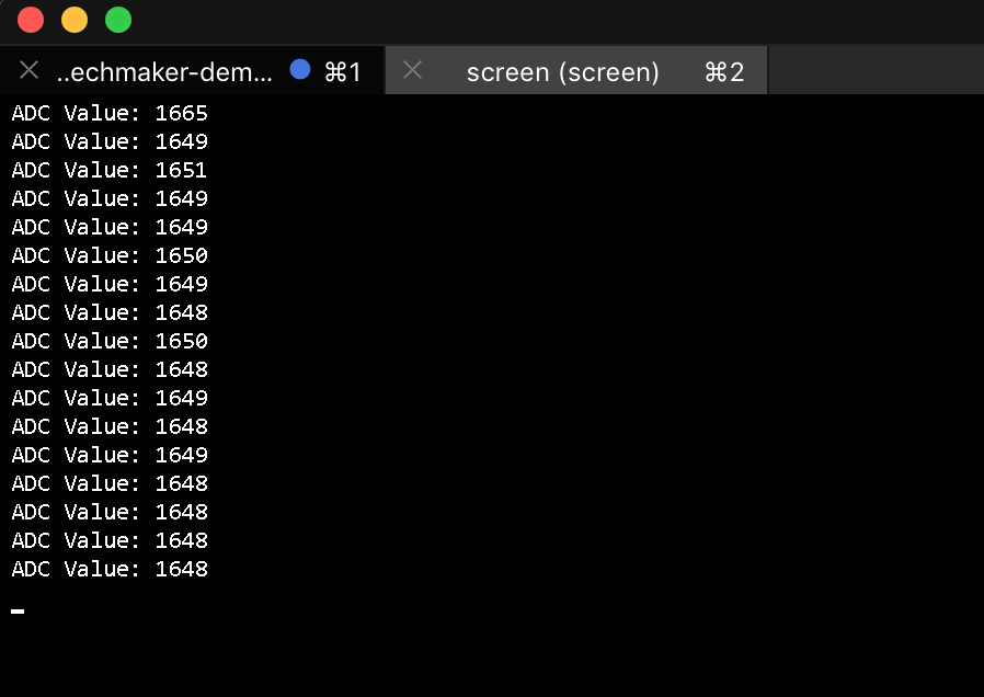
For example, take BlackPill board with STM32 MCU and a small firmware that checks the secret key (transmitted via UART) and either blocks the device (lines 30–37) or performs the basic functionality — sends ADC measurements every second via USB.
The full project code written in C for System Workbench for STM32 is located here.
Our embedded crackme :)
0x00 Firmware dump #
The first step is to get a device memory dump. This can be achieved either by downloading firmware updates from the official website or by reading the flash memory of the device itself.
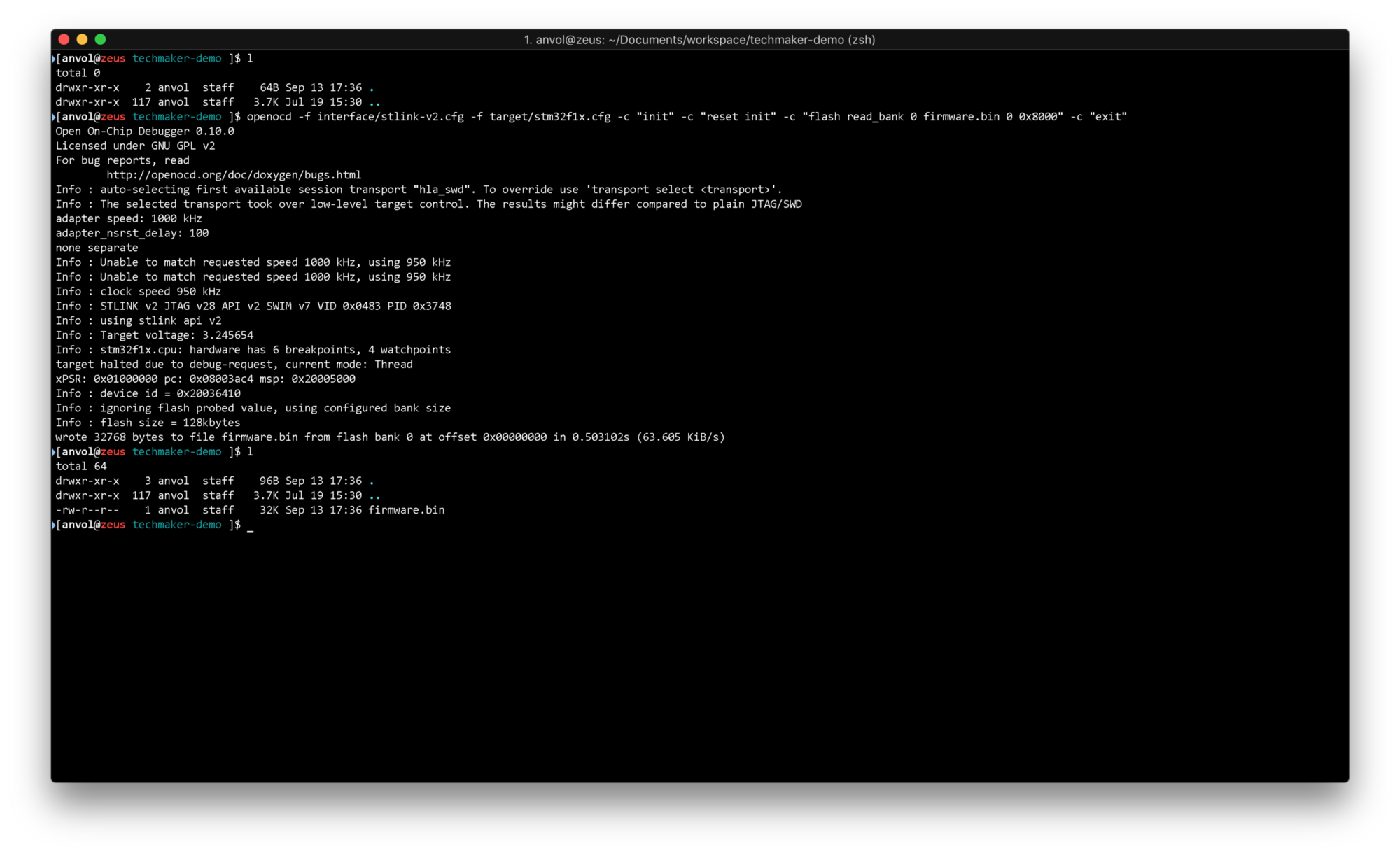
The following OpenOCD command downloads the first 32kB of the device flash memory.
openocd -f interface/stlink-v2.cfg -f target/stm32f1x.cfg -c "init" -c "reset init" -c "flash read_bank 0 firmware.bin 0 0x8000" -c "exit"
Try changing the command in a way, so that you download all 64kB of BlackPill’s flash memory. By the way, there is actually 128kB present and the programmed limit of 64kB can be bypassed ;)
0x01 Quick analysis #
A quick analysis will give us an understanding:
- is the flash content encrypted?
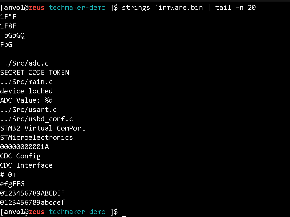
- which string literals are present in the firmware?
Any of the following tools can do the job for us: strings, binwalk, https://binvis.io .
strings firmware.bin
File visualization allows you to evaluate the entropy of different parts of the file and to detect the presence of text information. Use https://binvis.io/ and download firmware.bin for visual analysis.
0x02 Disassembly #
We will use radare2 as a disassembler. ARM Cortex-M uses the Thumb instruction set. From the official ARM documentation:
The Thumb instruction set is a subset of the most commonly used 32-bit ARM instructions. Thumb instructions are each 16 bits long, and have a corresponding 32-bit ARM instruction that has the same effect on the processor model. Thumb instructions operate with the standard ARM register configuration, allowing excellent interoperability between ARM and Thumb states. On execution, 16-bit Thumb instructions are transparently decompressed to full 32-bit ARM instructions in real time, without performance loss. Thumb code is typically 65% of the size of ARM code, and provides 160% of the performance of ARM code when running from a 16-bit memory system.
In other words, the instructions are 16-bit and are expanded to 32-bit in hardware.
Let’s recall what the function calls and conditional transitions in ARM look like:
+------------------+------------+
|   Instruction    | Relativity |
+------------------+------------+
| b label          | Relative   |
| bx register      | Absolute   |
| bl label         | Relative   |
| blx label        | Relative   |
| blx register     | Absolute   |
| pop {..., pc}    | Absolute   |
| ldr pc, =address | Absolute   |
+------------------+------------+
As we see two instructions are used to organize conditions and loops:
- cbnz (compare, branch on non-zero),
- cbz (compare, branch on zero).
Entry point #
For stm32f1xx MCUs the documentation provides the following information on workflow and code entry point:
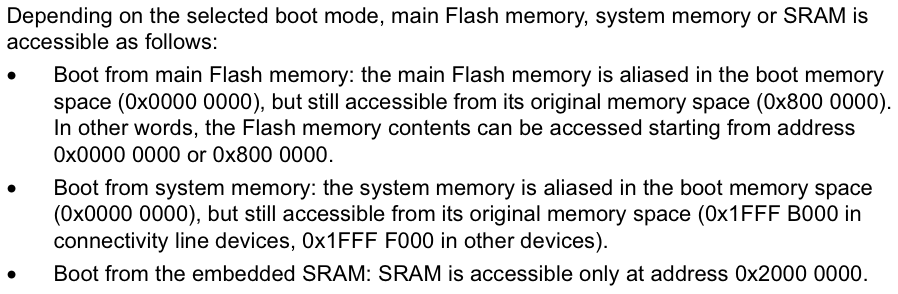
The point from which the execution begins — is the ResetHandler. In the interrupt vector, there is a 0x04 shift from the beginning of the flash (Reset_Handler @ 0x0800 0004).
Talk is cheap. Show me the code! #
r2 -a arm -b 16 -m 0x08000000 -w firmware.bin
Here we launch radare2 specifying the ARM architecture with the instruction set to be 16-bit, set start address offset to 0x08000000, enable firmware editing and binary file path.
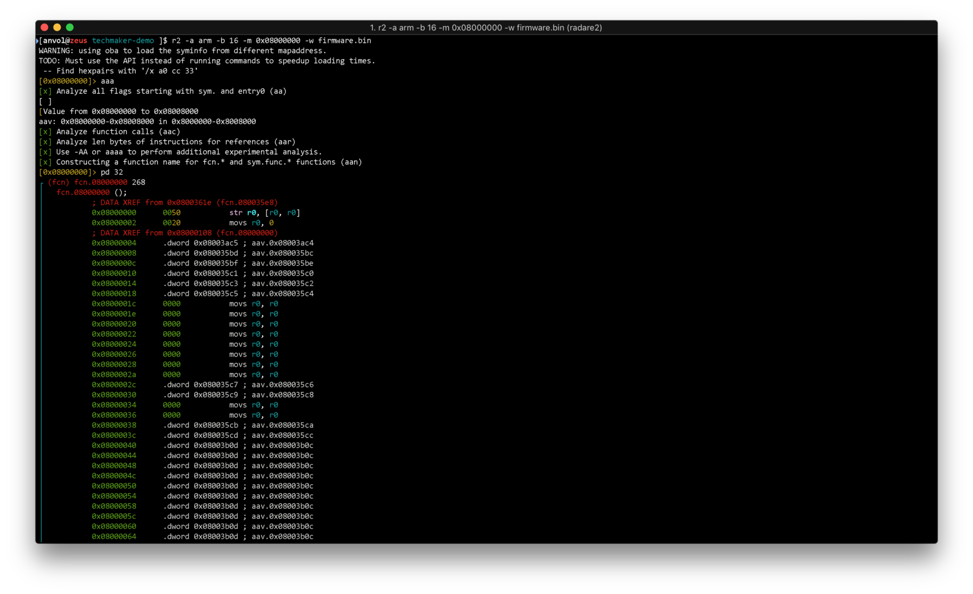
ааа command is used to analyze calls, jumps, and symbols and give them auto-generated names.
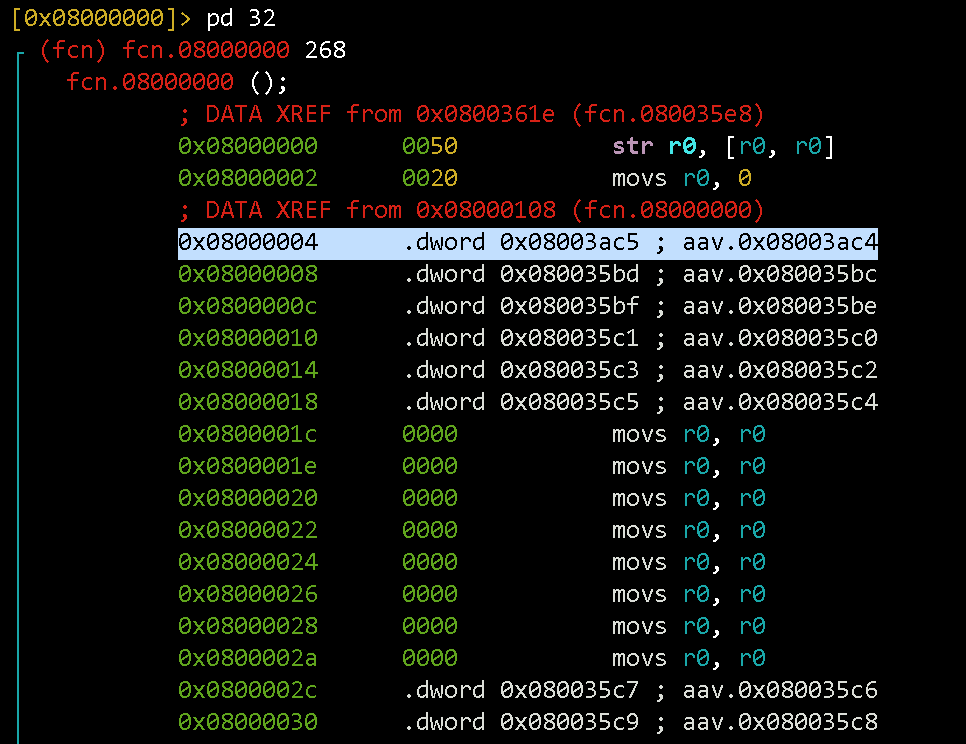
pd 32 command outputs 32 commands starting from the current offset. It is indicated to the left of the cursor (0x08000000 in yellow, so it is at the beginning of the file).
Let’s analyze ResetHandler. We shift to 0x08003ac4 and output disassembly:
s aav.0x08003ac4pd 32
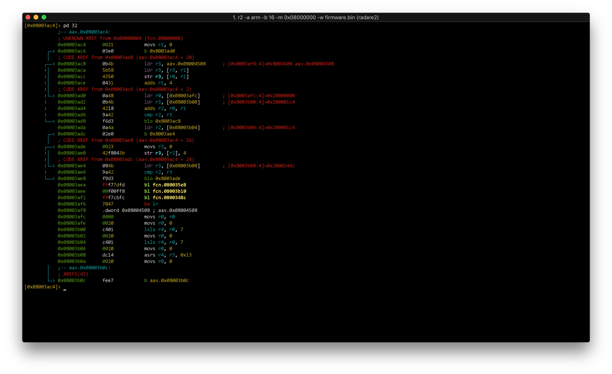
Immediately we see 3 function calls (bl fcn.08003xxx). Which are these functions? Let’s look at the project file /startup/startup_stm32f103xb.s and find the matches.
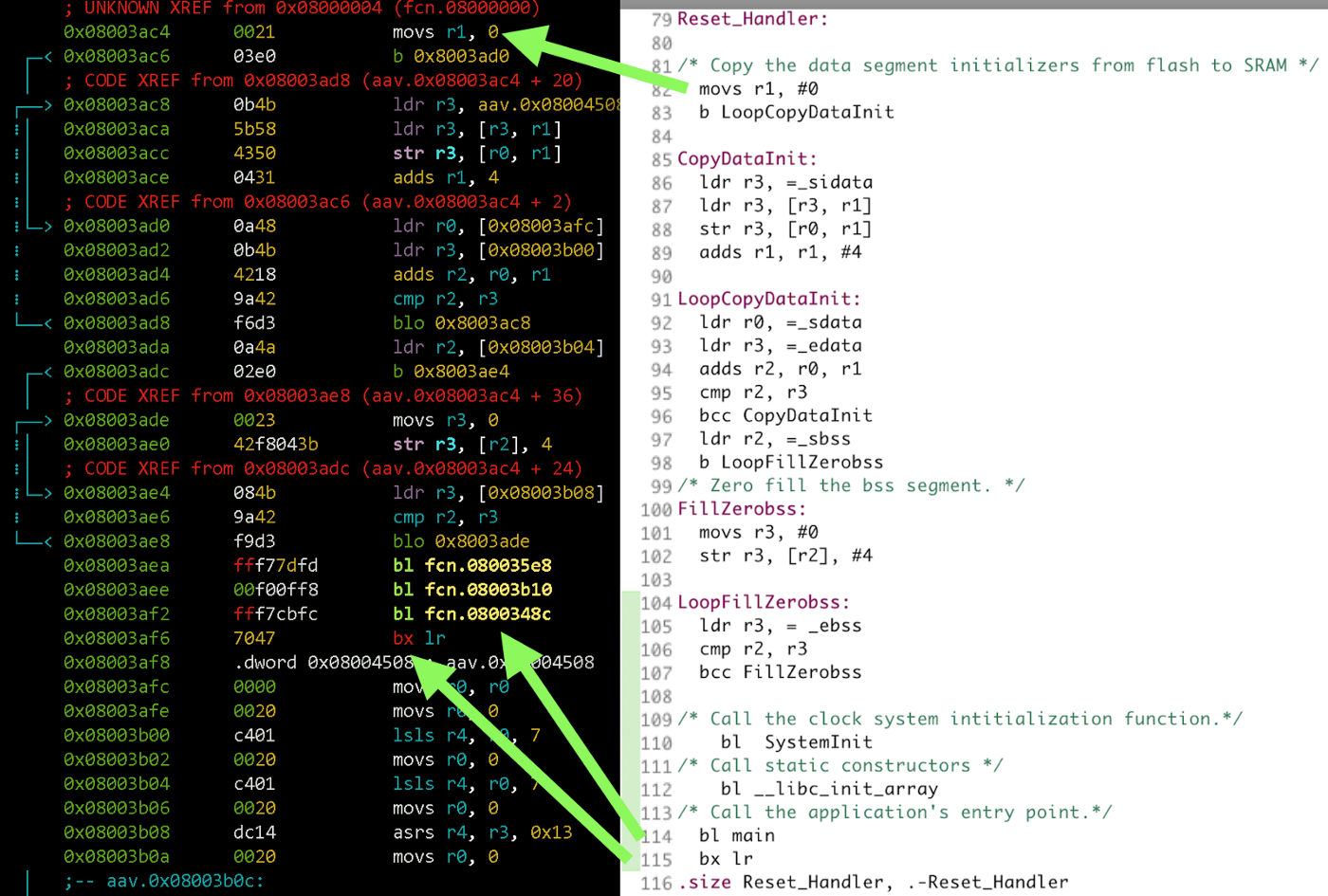
Three function calls are SystemInit (clock setup and flash initialization), libc_init and main. Let’s go to main and output the function listing:
s fcn.0800348cpdf
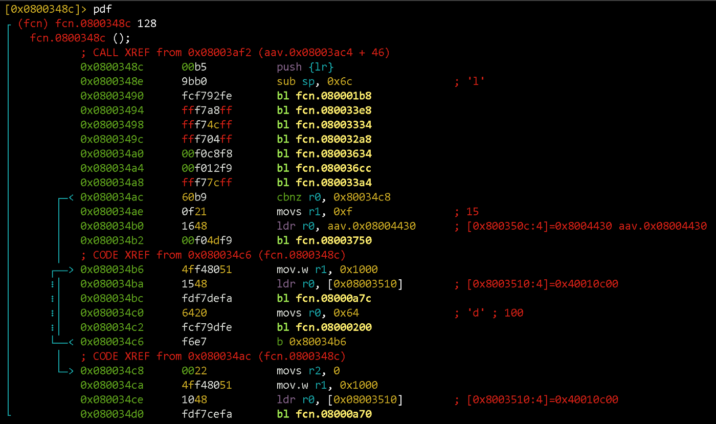
In the beginning, the call address is stored and space for the local variables are allocated on the stack (it grows downwards, so the stack pointer simply subtracts the required number of bytes).
Next up are function calls that initialize different peripherals. After that, two loops are located with a conditional jump to one of them. It’s easier to inspect them by rendering the transition graph:
VV
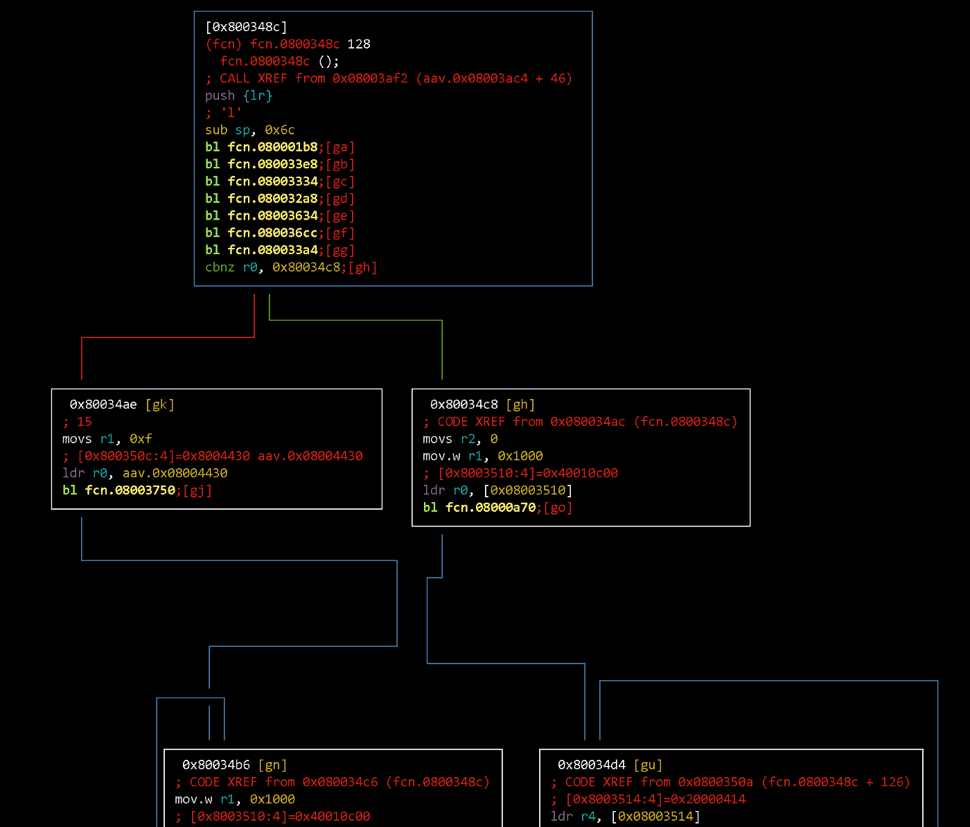
If r0 register has a non-zero value after calling 33a4 function, the flow will go to the right. Hence, if r0 has zero value — the left branch is executed.
0x03 Patch #
On the left, the pointer to something (aav.0x08004430) is loaded into the registry r0. Let’s see what is there. We output 32 values starting at address aav.0x08004430:
x 32 @ aav.0x08004430
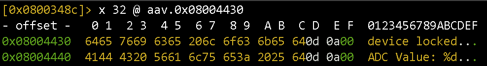
So, going to the left branch of the graph, we fall into the loop that blocks the device. We need to change the conditional jump.

There are two options:
- invert it (
cbnz->cbz) - replace it with an unconditional jump to the address
0x80034c8(location of main code that does ADC measurements, etc.)
An unconditional jump will make the firmware pass the check regardless of the condition, and the inversion — will work only in the absence of a key.
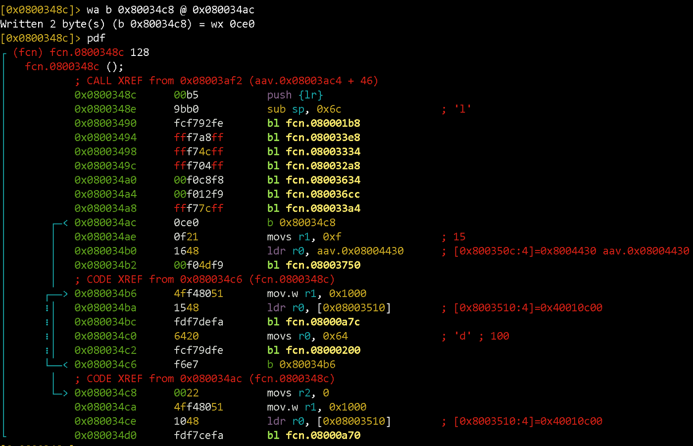
We will place an unconditional jump instead of cbnz:
wa b 0x80034c8 @ 0x080034ac
wa command writes the opcodes corresponding to the assembly line “b 0x80034c8” at the offset 0x080034ac.
0x04 Upload & test #
Let’s upload the modified firmware to the device and make sure it works.
openocd -f interface/stlink-v2.cfg -f target/stm32f1x.cfg -c "program path/to/firmware.bin verify reset exit 0x08000000"
screen /dev/cu.usbmodem1421
0x05 DIY #
The key check function can be called from different locations in the firmware. It is, therefore, more efficient to patch the isUnlocked function so that it returns a non-zero value regardless of the key being present. Try that yourself 😎