Our last year’s badge for NoNameCon received surprisingly positive feedback from conference visitors. A whole fan community emerged around it that has since created numerous projects using badge hardware. Now that we have a certain level of expectations set let’s dive deep into implementation 😎
This year, the concept of the badge has changed a bit. We decided not to use ready-made dev boards, but to develop the entire board from scratch.
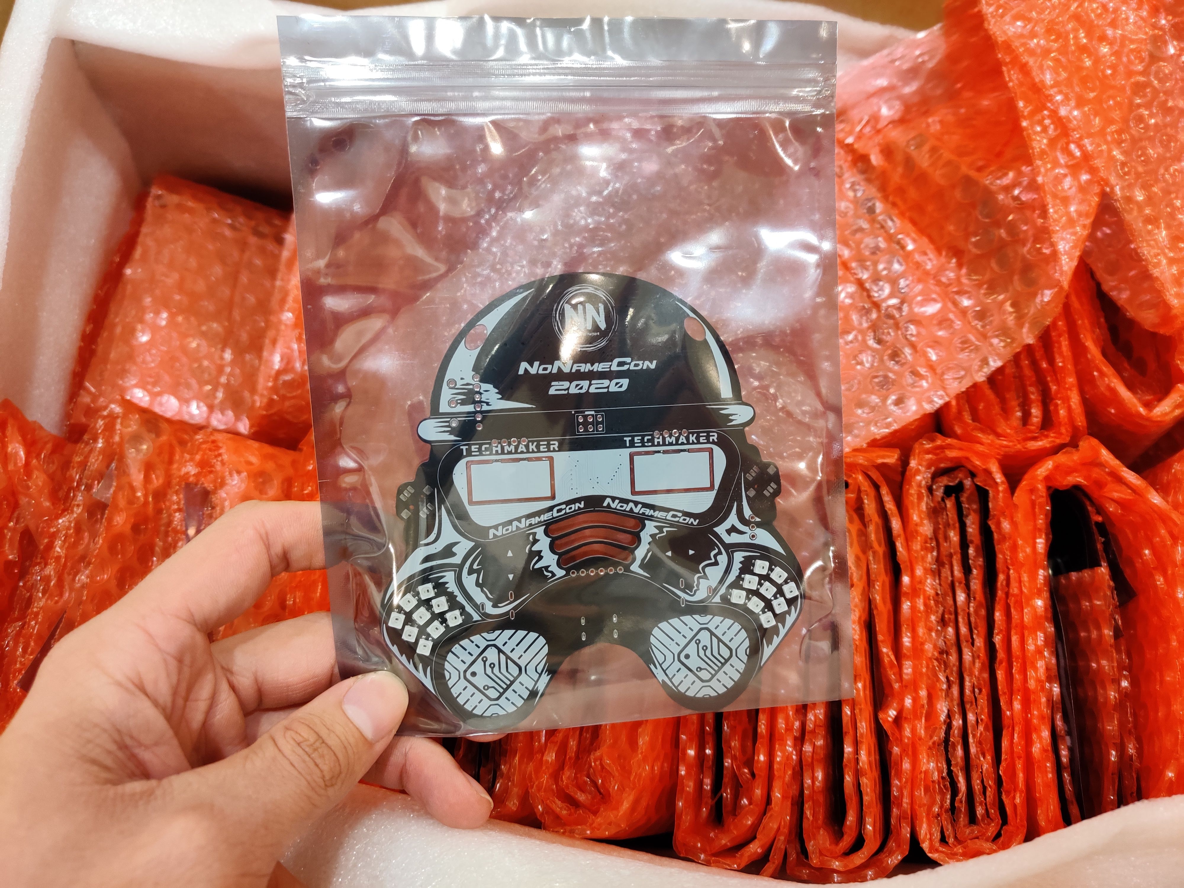
This increased the cost of the badge by about 50 percent. On the other hand, after receiving the batch from the Chinese PCB warehouse, the only thing we need to do is flash the firmware. Say goodbye to heroic volunteer suffering and hurting fingers from soldering for numerous hours.
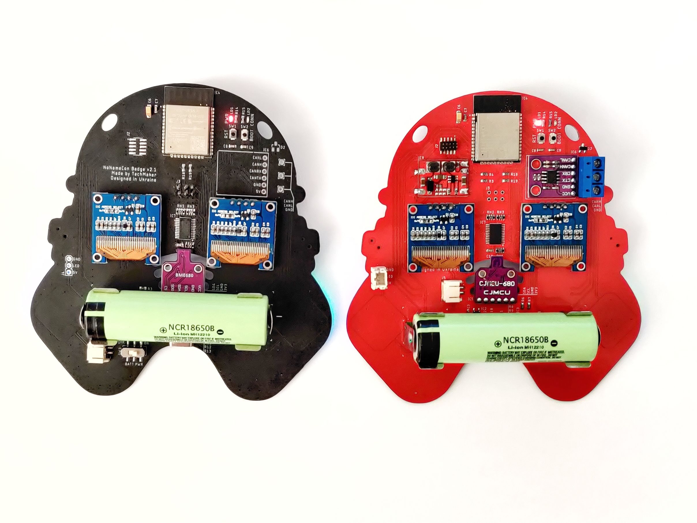
Red & black #
The development was done in two iterations. There’s nothing special to be described: slightly simplified the battery supply scheme, added power protection, and a killswitch. Everything else turned out to be working in both versions.
Creators Edition #
The badge was designed for a specific functionality - air quality monitoring, which includes temperature, humidity, pressure, and indoor air quality indicator (IAQ), which use volatile organic compounds (VOCs) measurements as well.
VOCs are organic chemicals that have a high vapor pressure under normal conditions - this allows them to be present in the air in significant concentrations. VOCs include a wide range of organic compounds such as hydrocarbons, aldehydes, alcohols, ketones, terpenoids, and others.
This functionality is optional, available only to those who have purchased NoNameBadge Supporter Ticket. Everybody else will be able to buy additional components (available in numerous hardware stores) and solder them by themselves.
What does NoNameBadge Supporter Ticket include?
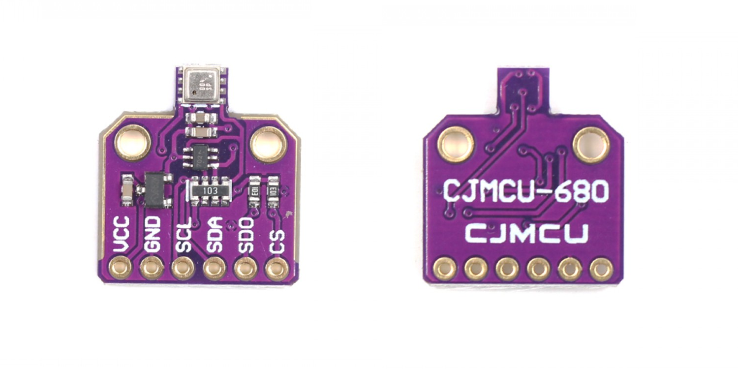
- BME680 environmental sensor
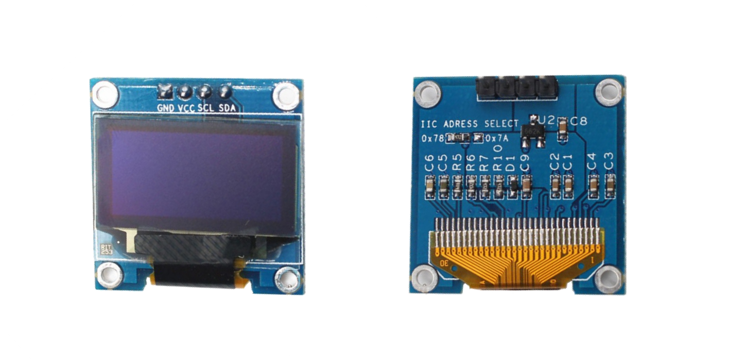
- 2 OLED screens
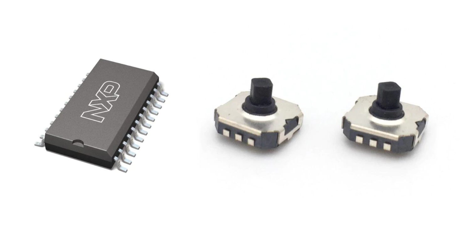
- 2 joysticks
- 18650 battery holder and power switch
- USB Type-C cable for connecting the badge to the power supply or computer
- our gratitude for the development support (a tiny surprise)
- keyring with logo from the badge visor
Kidding :) We’ll keep the logo keyrings.
Badge firmware automatically detects the presence of sensors and displays. The display will show Temperature (C), Humidity (%), Pressure (hPa), and IAR (index). LEDs on the badge work in a “traffic lights” style to give an understanding of whether everything is good, not so much, or very bad :)
Do you see yellow? - ventilate the room 😝 Do you see red? - time to take out the garbage 😁
Optionally, you can take our firmware and modify it to work with your own server via HTTP or MQTT.
⚠️⚡ The 18650 battery terminals together with the metal lid of your laptop can relatively easily create an unforgettable experience of observing the electric welding process. ⚡⚠️
⚠️⚡ CAUTION! DO NOT SHORT CIRCUIT THE BATTERY! ⚡⚠️
Or do that, film it, get burnt and earn millions of views on social networks ¯\_(ツ)_/¯
Basic Edition #
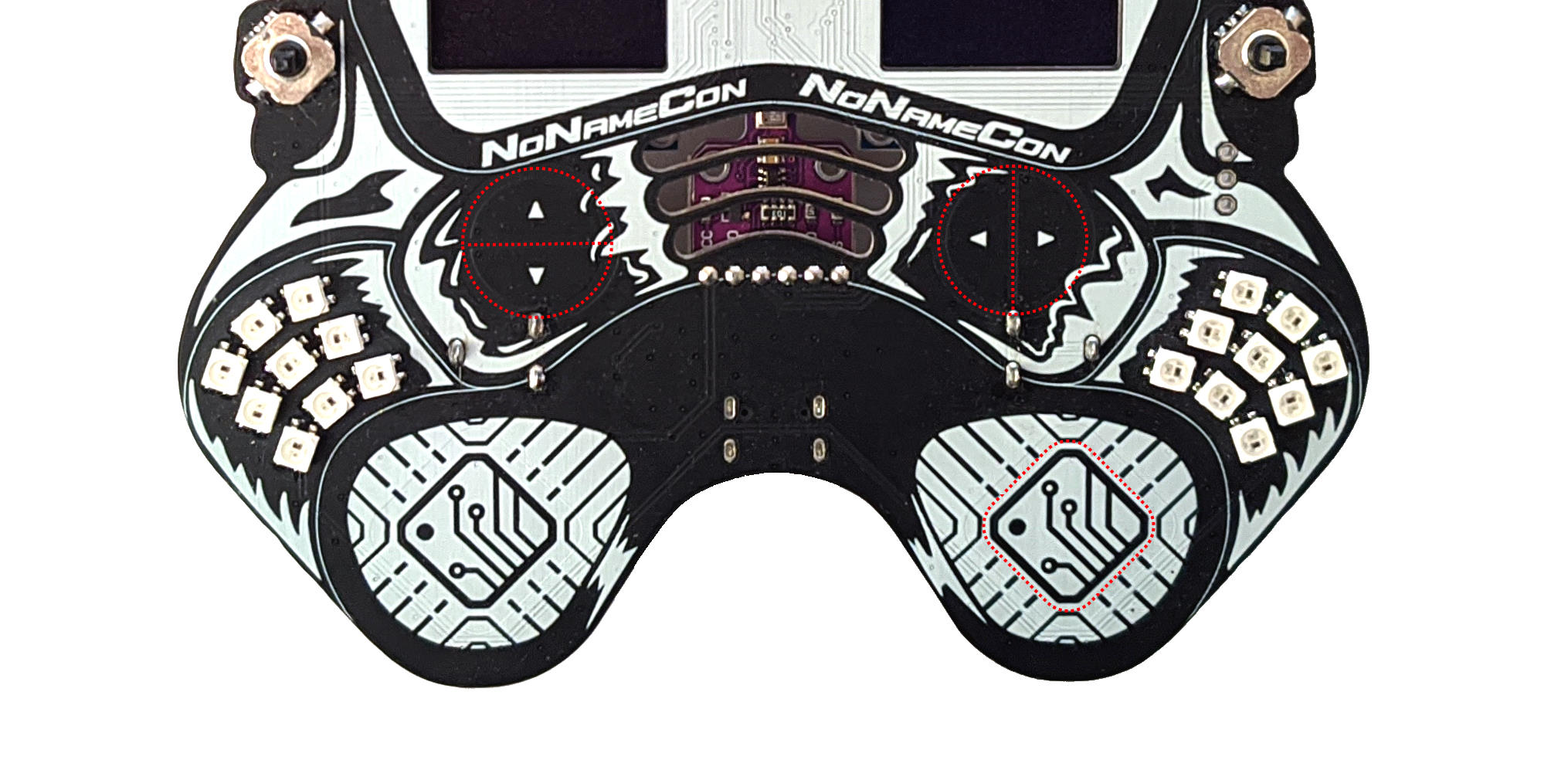
The basic version contains touchpads for RGB LEDs control, a couple of regular LEDs, and a minimal set of components for power and programming ESP32 via USB Type-C. The firmware contains CTF tasks that start after establishing a connection to the badge via minicom / miniterm / putty / screen or similar serial terminal utilities.
For further firmware modifications and badge upgrades, we provide the source code of the public part of the firmware (without CTF) and the schematic of the badge hardware.
Bonus: there’s a footprint for soldering CAN bus module and a terminal block. We have an internal joke that whatever we do turns into CAN bus reverse engineering 🤨
Capture the Flag #
This section will be updated after the start of the conference. So far it is known that there will be 6-7 tasks related to cybersecurity of embedded systems. Some of the tasks are re-done due to COVID-19 epidemic, social distancing rules, and the absence of the offline part of the conference.
It is well known that all tasks are based on real vulnerabilities that we have encountered during our research and product development. Among them were industrial machines, network equipment, elements of the “smart home”, and some automotive products.
Last year we saw interesting approaches and problem-solving techniques. We hope that someone will be able to complete the 2020 set of tasks in the given time. The tasks are difficult but possible to solve. Some solutions have been tested for 3-4 months :) This is a period of time over which you forget the details and write the exploit from scratch rather than remember the nuances of implementation.
Special thanks to those who agreed to test the complexity of the tasks, sacrificing the pleasure of surprise and the spirit of competition!
Hardware Details #
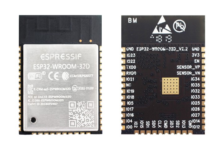
The badge is based on the Espressif ESP32-WROOM-32D module, documentation for it can be found on the official website.
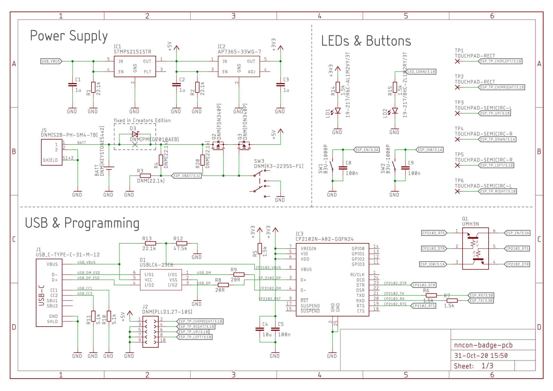
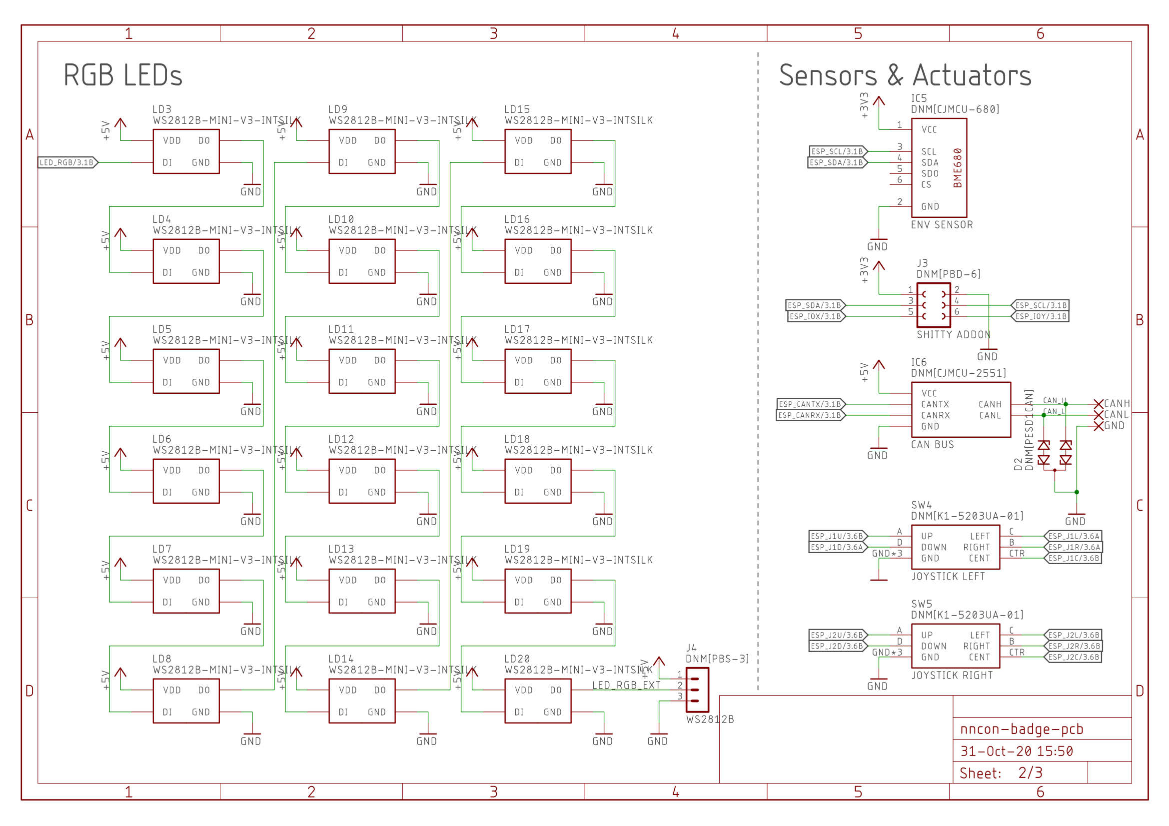
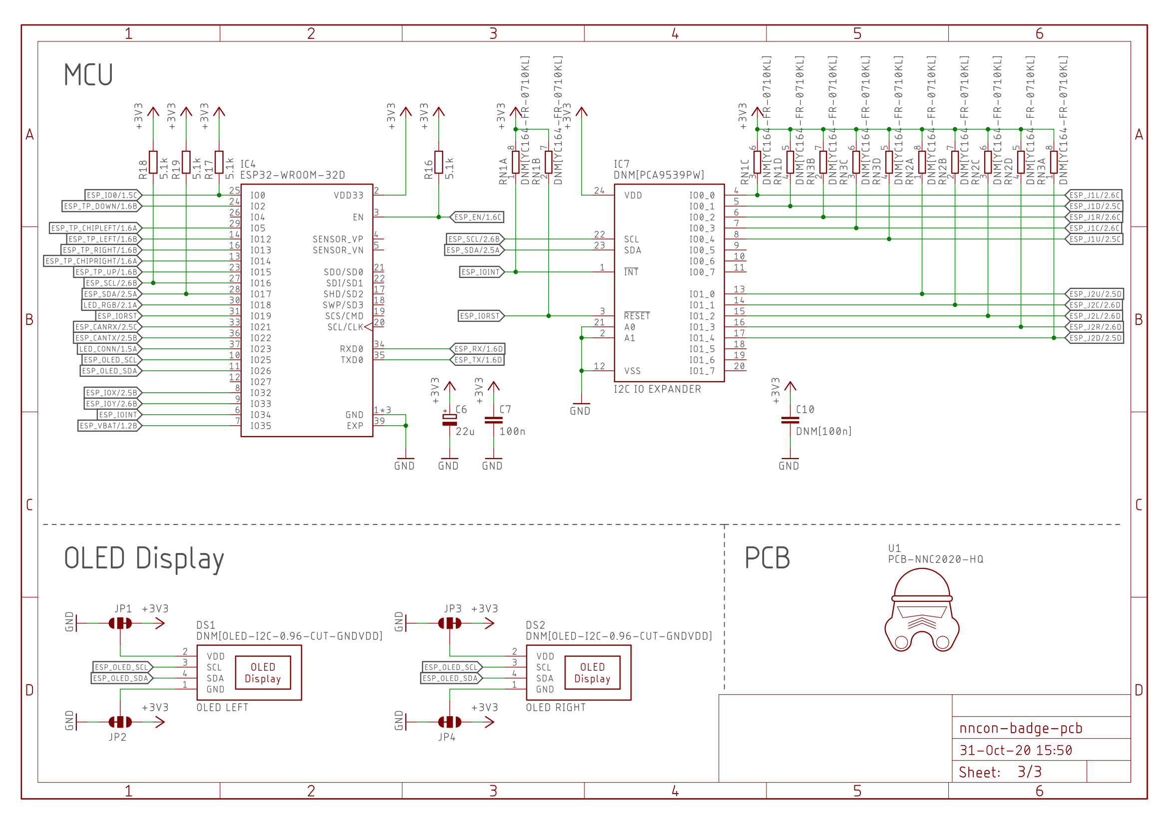
From a hardware point of view, the PCB in Creators Edition and Basic Edition are the same - the only difference is that not all components / modules are populated in Basic Edition. In the schematic, such components are labeled DNM (do not mount).
Black Badge Schematic (v2.1) in PDF format
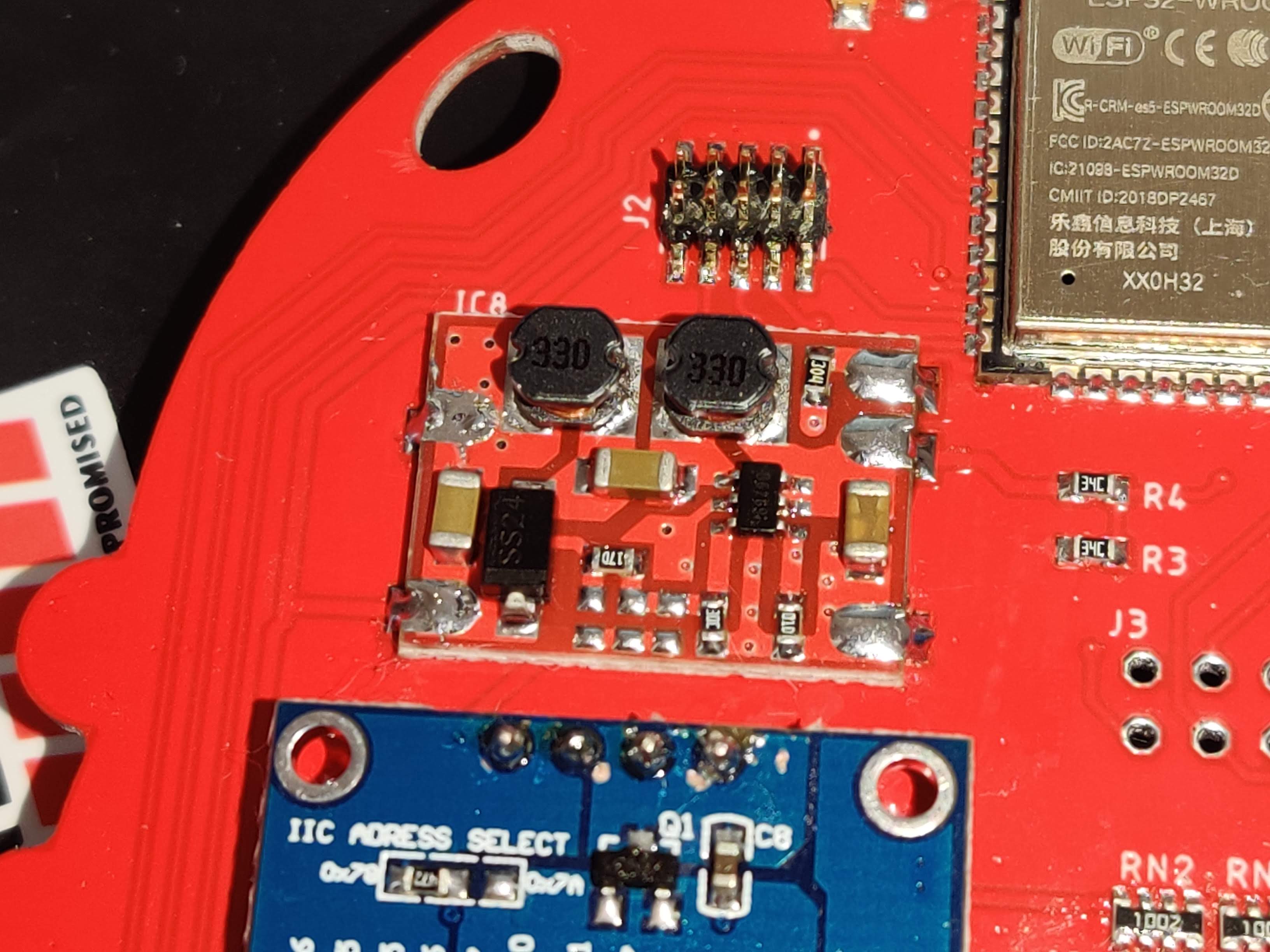
We couldn’t live without hotfixes :) We did not put protection against the reverse polarity of the battery, so Creators Edition ready-made boards were modified and soldered.
ESP32-WROOM Pinout #
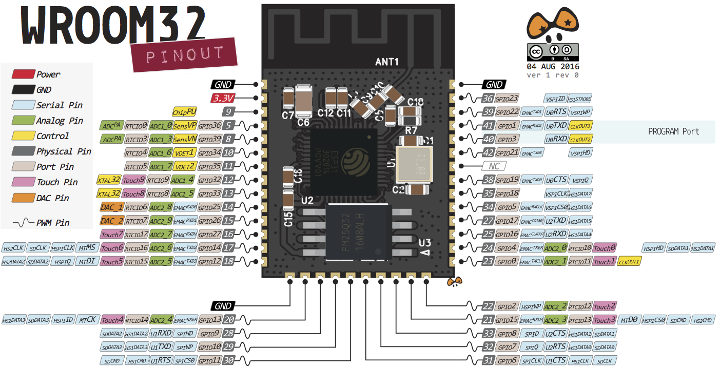
All pin functions of the ESP32-WROOM module are well described in the article by Random Nerd Tutorials. In general, due to usage of GPIO Matrix, you can set any peripheral output to any pin of the module. The image below shows the names of the pins and their main functions.
Badge Pinout #
All the main modules on the badge are connected to the pins of the microcontroller. Screenshot from the black badge schematic:
UART for Programming #
| Pin | Function |
|---|---|
| IO1 (U0TXD) | UART Tx |
| IO3 (U0RXD) | UART Rx |
| EN | UART DTR |
| IO0 (BOOT) | UART RTS |
The ESP32 MCU has an option to update the firmware via the UART interface. The board uses the CP2102N USB-UART converter to update the firmware, communicate with the badge via console and output logs. Pin EN performs the function of a microcontroller reset, MCU powers up when this pin has 3.3V on it. If during bootup pin IO0 has 3.3V voltage applied, the chip will start executing code, if 0V applied - it enters bootloader for firmware update. To automatically switch ESP32 to bootloader mode and back, the EN and IO0 pins are connected to the Harware Flow Control of CP2102N. They are also connected to “RST” and “BOOT” buttons for manual control.
I2C Bus #
| Pin | Function |
|---|---|
| IO16 | I2C0 SCL |
| IO17 | I2C0 SDA |
| IO25 | I2C1 SCL |
| IO26 | I2C1 SDA |
The following devices are connected to the I2C0 bus:
- BME680 - environmental sensor, has the address 0x77
- PCA9539PW - GPIO expander with joysticks connected, has the address 0x74
The following devices are connected to the I2C1 bus:
- SSD1306 OLED 0.96" screen (left), has an address of 0x3D
- SSD1306 OLED 0.96" screen (right), has an address of 0x3C
During firmware start, I2C0 and I2C1 buses are scanned for devices present. For Creators Edition badge you will see the following output:
I2C0: detected 2 devices
      [0x74] GPIO expander (Joysticks)
      [0x77] BME680
I2C1: detected 2 devices
      [0x3C] OLED right
      [0x3D] OLED left
TouchPads #
| Pin | Function |
|---|---|
| IO2 (TP2) | Down |
| IO15 (TP3) | Up |
| IO13 (TP4) | Right |
| IO12 (TP5) | Left |
| IO14 (TP6) | Chip (right) |
The black badge has five touch buttons: four arrows and a right-side TechMaker chip. The left-side chip is connected to the IO5 pin, which, unfortunately, does not have TouchPad functionality, so it is not available ¯\_(ツ)_/¯.
Buttons \ LEDs #
| Pin | Function |
|---|---|
| EN | RST Button |
| IO0 | BOOT Button |
| IO18 | WS2812 LEDs |
| IO23 | Blue LED |
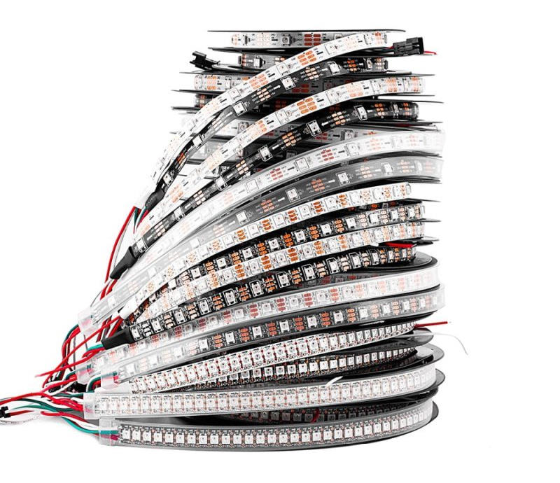
WS2812B-MINI-V3 addressable LEDs (also known as Neopixels) are used, and they are connected in series. There are total of 18 LEDs and the output of the last one is routed to the J4 connector so it’s possible to connect additional external LED strips \ matrices \ rings.
CAN Bus #
| Pin | Function |
|---|---|
| IO21 | CAN Rx |
| IO22 | CAN Tx |
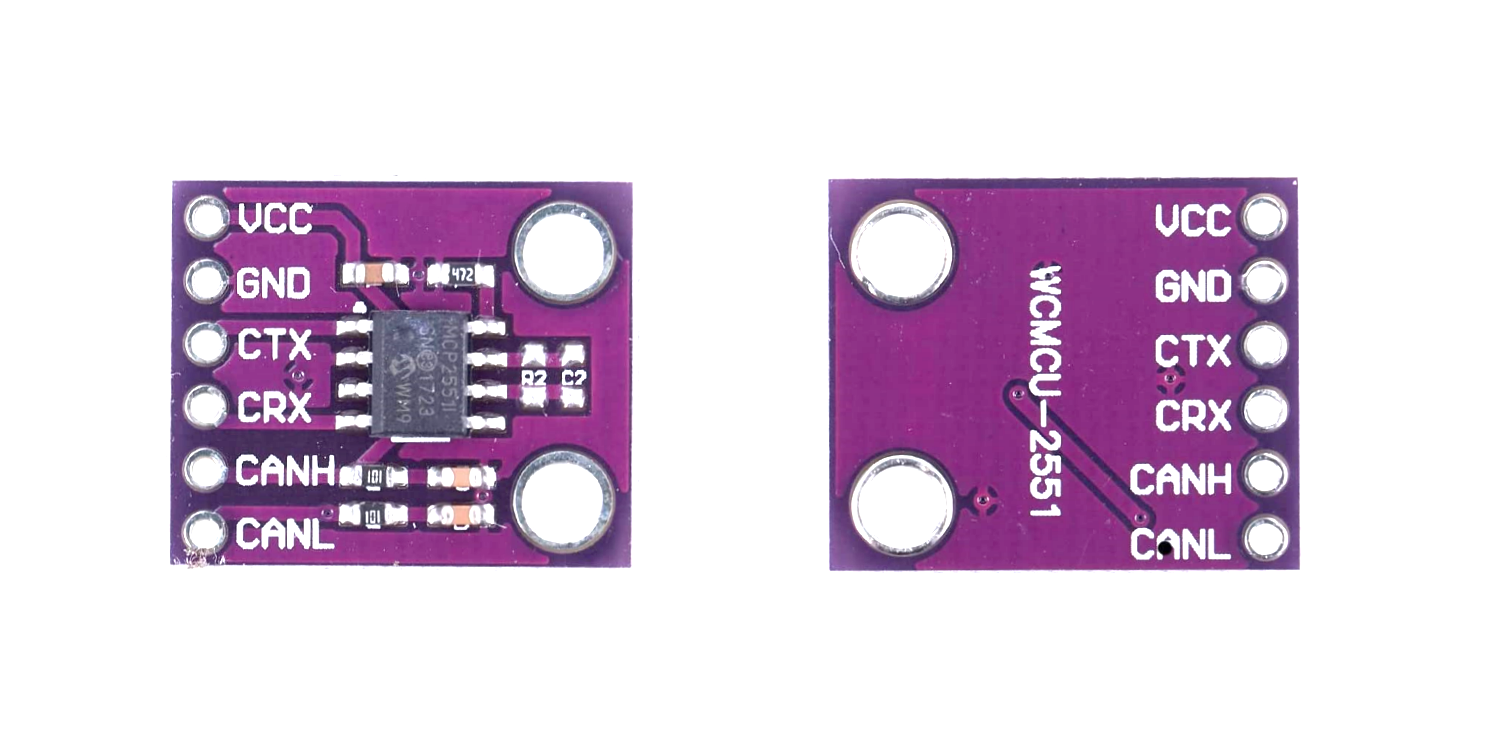
It is possible to connect the CAN bus transceiver module with a screw terminal block on the badge, but they are not included in any edition. The connector is made suitable for the CJMCU-2551 module, which is based on MCP2551 with 5V power supply.
Shitty Addon Connector #
| Pin | Function |
|---|---|
| IO16 | I2C0 SCL |
| IO17 | I2C0 SDA |
| IO32 | GPIO1 |
| IO33 | GPIO2 |
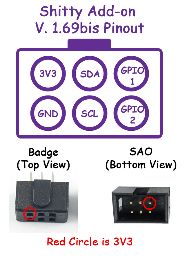
To expand the functionality of the badges on we added the DEFCON popular Shitty Addon Connector v1.69bis.
Where to buy #
Modules can be purchased on Aliexpress, or in maker stores like Adafruit, Sparkfun, etc.
- CJMCU BME680 Environmental Sensor
- OLED 0.96" I2C 4pin White Display
- Shitty Addon Connector
- External RGB LEDs
- To connect CAN bus:
- To connect Joysticks:
- Joystick ALPS SKRHABE010 (2 pcs.)
- GPIO Expander PCA9539PW (1 pcs.)
- Resistor Assembly 4x SMD1206 10кОм (3 pcs.)
- Capacitor SMD0603 100nF (1 pcs.)
- To connect rechargeable Li-Ion battery:
- Resistor SMD0603 22.1kOhm 1% (3 pcs.)
- Transistor MOSFET P-channel FDN340P SOT-23 (2 pcs.)
- Switch MSS-2235S (1 pcs.)
- 18650 Battery Contact Keystone 54 (2 pcs.)
- Battery Socket JST PH2.0 2pin (S2B-PH-SM4-TB) (1 pcs.)
- Schottky Diode PMEG2010AEB SOD-523 1A (1 pcs.)
Stay tuned #
Here we will post links to additional materials: diagrams, code, instructions, etc.
These are the guys you wanna punch in case your badge is faulty:

